A water tube boiler carries water and steam inside tubes heated externally by combustion gas. Water-tube construction is selected when design pressure, steam capacity, or solid fuel firing exceeds what a shell boiler carries economically. Which of those three settles the question for a given plant depends on peak simultaneous steam demand, the design pressure and any superheat requirement, and the fuel properties the site can guarantee year-round. Tube and drum geometry fix the pressure and capacity envelope at fabrication. Fuel efficiency comes mostly from heat-recovery accessories and combustion control, which both constructions can carry, making it a weak basis for choosing between them.

Dimension | What it means for water-tube construction |
Heat-transfer arrangement | Water and the steam-water mixture flow inside the tubes; combustion gas flows over the outside |
Furnace enclosure | Water-cooled tubes welded into a gas-tight membrane wall form the furnace envelope in most modern industrial designs |
Circulation modes | Natural (density-driven), forced (pumped), or once-through; depends on design pressure and the design family specified |
Common US construction code | ASME BPVC Section I, where specified by the purchaser or adopted by the governing jurisdiction |
EU regulatory framework | Pressure Equipment Directive 2014/68/EU sets the essential safety requirements; the EN 12952 series is the harmonised-standard route for water-tube boilers |
Pressure parts inside code scope | Under Section I, superheaters and economizers connected directly to the boiler without an intervening valve are treated as part of the boiler |
Fuel properties that drive design | Heating value, moisture, ash, volatile matter, particle size, and the seasonal variation in all five |
What a Water Tube Boiler Is, and What Sets Its Pressure Ceiling
Water-tube construction carries the pressurised water in small-diameter tubes, where a shell boiler holds it in one large vessel, and the wall thickness a given pressure demands falls as diameter falls. Design temperature, material allowable stress, and the manufacturing factors the applicable code requires all bear on the final figure.
The reverse arrangement, hot gas travelling inside tubes surrounded by a water-filled shell, is the fire-tube boiler. Both produce steam. What separates their pressure envelopes is largely geometric.
For a thin-walled cylinder under internal pressure, the required wall thickness can be approximated as pressure multiplied by radius, divided by the allowable stress of the material. The approximation assumes a uniform wall and sets aside corrosion allowance, bend thinning, weld or manufacturing factors, tube ligament effects, and the reinforcement needed around openings. Treat it as a scaling argument, not a design calculation.
Hold pressure and material constant and only the radius term moves. A shell of roughly 2 m diameter and a tube of roughly 50 mm outside diameter differ by a factor of about forty in radius. The shell therefore needs about forty times the wall thickness to carry the same internal pressure. Substitute your own geometry and the ratio changes. Read it as a geometric scaling illustration, not a comparison of two code-compliant components; a real comparison would also turn on design temperature, allowable stress at that temperature, and the specific code formula.
That scaling explains why raising pressure in a shell design becomes uneconomic well before the steel runs out of strength. Thickness has to increase across a very large surface, which drives plate mass, forming difficulty, welding time, and inspection burden together. Moving the water into tubes collapses the radius term and lets the same material family carry far higher pressure at a fraction of the wall thickness.
Two code frameworks describe the result. ASME BPVC Section I, the construction rules for power boilers, applies where a purchaser specifies it or a jurisdiction has adopted it. Within its stated scope it covers boilers generating steam above 15 psig and high-temperature water boilers above 160 psig or 250°F. It also treats superheaters and economizers connected directly to the boiler without an intervening valve as part of the boiler. In the European Union, the legal instrument is the Pressure Equipment Directive 2014/68/EU, which sets essential safety requirements for stationary pressure equipment above 0.5 bar. The EN 12952 series is the harmonised standard written for water-tube boilers, and building to it confers a presumption of conformity. A manufacturer may also demonstrate equivalence by another route, verified by a notified body.
Two code developments worth checking before a specification is issued
· ASME BPVC 2025 Edition, issued 1 July 2025, superseding the 2023 edition of Section I. The code is republished on a two-year cycle. Action: name a specific edition in the enquiry, and confirm which edition the inspecting jurisdiction has adopted.
· EN 12952-1 revision at final draft stage. The part currently in force dates from 2015. Action: ask the notified body which edition governs the conformity assessment route for your project before the specification goes out.
For a buyer, one consequence is worth isolating. Design pressure sets wall thickness across every pressure part, and thickness is paid for in material, welding, and examination at fabrication rather than in operation. Check that the stamped nameplate and the code data report carry the pressure you specified.

The Water and Steam Circuit, and What Each Component Does On It
The water and steam circuit of a water tube boiler runs from feedwater inlet to steam outlet through a fixed sequence of pressure parts, and how much of that circuit a particular boiler contains depends on operating pressure and on whether superheat and heat recovery are in scope.
1. Economizer to steam drum. Feedwater passes through the economizer, picking up heat from flue gas that has already left the furnace, then enters the steam drum under level control.
2. Steam drum to lower drum or headers. Unheated downcomers carry cooler water from the drum down the outside of the gas path to a mud drum or to lower headers at the base of the furnace.
3. Through the heated surface. Membrane waterwall tubes take radiant heat from the flame and the convective tube bank takes heat from cooling flue gas. Part of the water flashes to steam, and the steam-water mixture rises through the risers.
4. Separation in the steam drum. Cyclone separators and demister pads strip water droplets from the mixture. Separated water rejoins the downcomers; dry saturated steam collects above.
5. Superheat and outlet. Where a turbine or a process requires it, saturated steam passes through a superheater sitting in the high-temperature gas path before leaving the boiler.
Circulation around steps 2 to 4 is driven by density difference. The steam-water mixture in the heated risers is lighter than the column of water in the downcomers feeding them, so the heavier column falls and the lighter one rises without a pump. Designers express the margin as a circulation ratio, the mass of water passing through the evaporator divided by the steam generated. A higher ratio keeps tube surfaces wetted; when the ratio falls too far, steam can blanket a hot surface and local metal temperature climbs.
Within part of the stable operating range this loop is self-reinforcing, since more firing produces more steam and lowers riser density further. Buoyancy head and pressure losses around the whole circuit together set the actual mass flow, which is why circulation needs verifying across the full load range.
Physics also sets a ceiling here that tube layout cannot lift. As saturation pressure rises, the densities of saturated water and saturated steam converge toward each other and meet at the critical point. Buoyancy head is proportional to that density difference, so the driving force for natural circulation weakens as pressure climbs. That single relationship is why forced-circulation and once-through designs appear at the high-pressure end of the range and why natural circulation dominates below it.
When a burner is retuned for higher output without confirming that circulation and heat-flux limits still hold, furnace-wall tube metal temperature can rise above its design basis. Damage then shows up as oxide growth, swelling, creep, or eventual rupture, and which of those appears depends on water chemistry, flow distribution, fuel, and fireside condition.
A technical review should therefore include evidence that circulation margin, tube-metal temperature, and applicable heat-flux limits have been checked at more than one load point. The circulation ratio itself may sit in the thermal design summary or stay inside the manufacturer's controlled calculation package, and once-through designs do not use a recirculation ratio in the same sense.
Where the Water Tube and Fire Tube Line Actually Sits
The line between water-tube and fire-tube construction is drawn by pressure, capacity, and fuel form rather than by efficiency, and where a specific duty falls depends on which of those three first exceeds what a shell can carry. Efficiency is the most common reason given for choosing water-tube construction and the weakest one.
Combustion efficiency is governed by excess air control, burner turndown, and how completely the fuel burns. Thermal efficiency is governed mostly by how much heat is recovered from flue gas before it leaves the stack, which means the economizer, the air preheater, blowdown control, and condensate return. All of those can be fitted to either construction. Two units of identical construction, one with heat recovery and one without, will differ more from each other than a water-tube and a fire-tube unit with matched accessories.
The second claim worth slowing down on is safety. A shell boiler and a water-tube unit hold different inventories of pressurised water in differently shaped pressure parts, and water-tube construction distributes the working fluid among tubes, drums, and headers. That changes the failure profile without removing the possibility of a major pressure-part failure. Both constructions still depend on level controls that work and safety devices that have been tested on the unit itself. The risk changes shape; it does not disappear.
Where steam demand has grown past the pressure or capacity envelope the plant was originally specified for, re-check the sizing basis set at commissioning first. A boiler of either type running outside its design envelope behaves badly in ways that resemble a design defect.
A full side-by-side comparison of the two constructions, covering capital cost, erection time, and the maintenance skill each demands, belongs in a dedicated fire tube and water tube boiler comparison.
Design Families and What Each One Is Selected For
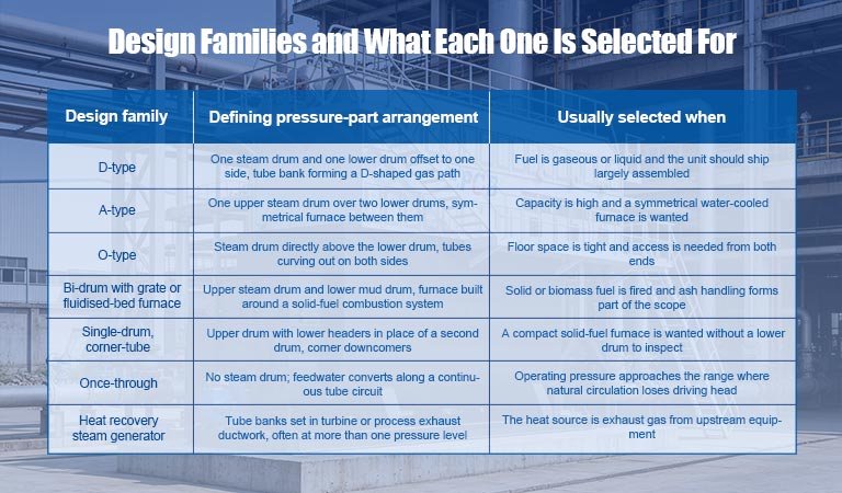
Water-tube design families are distinguished by how drums, headers, and tube banks are arranged around the furnace, and which arrangement suits a plant depends on fuel properties, required capacity, and the space available for erection.
Design family | Defining pressure-part arrangement | Usually selected when |
D-type | One steam drum and one lower drum offset to one side, tube bank forming a D-shaped gas path | Fuel is gaseous or liquid and the unit should ship largely assembled |
A-type | One upper steam drum over two lower drums, symmetrical furnace between them | Capacity is high and a symmetrical water-cooled furnace is wanted |
O-type | Steam drum directly above the lower drum, tubes curving out on both sides | Floor space is tight and access is needed from both ends |
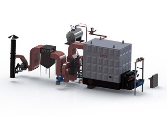
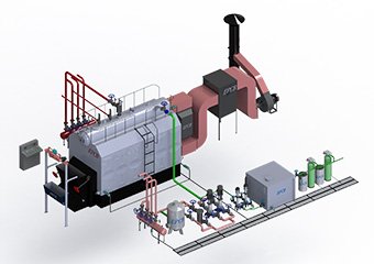
Bi-drum with grate or fluidised-bed furnace | Upper steam drum and lower mud drum, furnace built around a solid-fuel combustion system | Solid or biomass fuel is fired and ash handling forms part of the scope |
Single-drum, corner-tube | Upper drum with lower headers in place of a second drum, corner downcomers | A compact solid-fuel furnace is wanted without a lower drum to inspect |
Once-through | No steam drum; feedwater converts along a continuous tube circuit | Operating pressure approaches the range where natural circulation loses driving head |
Heat recovery steam generator | Tube banks set in turbine or process exhaust ductwork, often at more than one pressure level | The heat source is exhaust gas from upstream equipment |
Letter names describe geometry, not capability. Two D-type units from different builders can differ more in furnace volume and heat release per unit volume than the shared letter suggests, and that difference decides how each behaves on a marginal fuel.
At a given steam duty, fuel properties can change the furnace volume required by a wide margin. Solid fuels generally need more residence time to burn out and more space to disengage ash than clean gaseous fuels. A solid-fired furnace is therefore usually the larger of the two for equal output, and the size of the gap follows moisture, ash content, and reactivity. A furnace sized on a design fuel and then fed a wetter or higher-ash seasonal supply behaves like an undersized furnace, showing unburnt carbon in the ash and a falling steam rate.
Furnace geometry is what we ask each bidder to quantify. Request furnace volume and heat release per unit volume from every candidate design, then test both against the worst fuel analysis the site expects to receive. That figure is usually a different document from the sample that arrived with the tender.
The Variables That Decide Whether the Duty Needs Water-Tube Construction

Selecting water-tube construction turns on a small set of variables that must converge before drawings are released, and which of them binds first depends on whether pressure, capacity, or fuel is the constraint a shell design cannot meet.
Design pressure, design temperature, and peak simultaneous steam duty together establish the pressure-part and heat-transfer design basis. They strongly constrain drum thickness, heating-surface area, circuit count, and tube arrangement, though final tube diameter also reflects circulation requirements, allowable pressure drop, and the builder's manufacturing practice. Fuel properties have to converge alongside them, because they set furnace volume and the combustion system, and a furnace cannot be enlarged after erection.
What the construction buys is a pressure and capacity envelope a shell cannot reach economically, the ability to superheat, and a furnace geometry that accommodates solid fuel. What it costs is a stricter water chemistry regime, more control complexity, a longer erection programme, sensitivity to circulation and tube-metal temperature, and a higher standard of operator and maintenance skill. Both halves of that trade are structural, and accessory selection leaves them where they are.
Accessories and control philosophy can be refined after commissioning, with one distinction worth holding onto. Set points are adjustable: drum level, excess air targets, blowdown rate, and chemistry limits can all be tightened later. Physical decisions are not. Material selection, pressure rating, tube geometry, deaerator capacity, and the condensate return path are committed at fabrication or at erection, and revisiting them means an outage and re-piping.
Duty signal | Points toward water-tube construction | Verify before deciding |
Steam demand exceeds what one shell boiler supplies at the required pressure | Yes | Peak simultaneous demand across all loads, measured, not summed from nameplate ratings |
Superheated steam is required for a turbine or a process | Often, particularly at higher pressure, temperature, or capacity | Superheat temperature, steam purity the downstream equipment tolerates, and whether a shell design with a superheater covers the duty |
Solid or biomass fuel will be fired | Usually | Guaranteed year-round fuel analysis including moisture, ash, and particle size |
Low pressure, modest capacity, clean gaseous fuel | Usually no | Whether expansion already on the capital plan moves the duty outside the shell envelope within the asset life |
Feedwater treatment to tight limits cannot be sustained | Depends | Whether the plant can staff and supply the treatment programme continuously, including through turnover |
Failing the pressure test does not settle the question. At least two other routes lead to the same construction, capacity and solid fuel firing, and a third deserves checking, which is whether planned expansion pushes the duty out of the shell envelope inside the asset's life. Run all three before concluding either way.
One case is worth stating against our own commercial interest. Where the duty sits at low pressure with modest capacity on clean gaseous fuel, a packaged shell boiler is normally the cheaper and simpler answer. Water-tube construction earns its cost once pressure, capacity, or solid fuel pushes past what a shell can carry.
What the Tube Geometry Commits You to After Commissioning
Choosing water-tube construction commits a plant to a feedwater quality standard for the life of the asset, and how tight that standard must be depends on operating pressure and on the heat flux the furnace tubes see.
Scale on the waterside surface adds a low-conductivity layer between the boiling water and the tube metal. Heat keeps arriving from the furnace at whatever flux the firing rate produces. The temperature drop across that added layer has to come from somewhere, and it comes from raising the metal temperature behind it. How far the metal temperature rises depends on deposit thickness and conductivity, local heat flux, circulation, and tube material, which is why furnace-zone tube life is as much a water chemistry outcome as a metallurgical one.
Make-up water rising because condensate return has quietly been lost somewhere in the distribution system is a common upstream cause. Indicators can include increasing make-up demand, higher chemical consumption, climbing conductivity or blowdown requirement, and greater carryover risk, and which of these appears first depends on the control strategy and the instrumentation in place. Running a condensate survey before investigating the boiler often saves a diagnostic cycle.
Our own check on a specification is to read the design feedwater and boiler water limits against what the site's existing treatment plant delivers on its worst day. A limit that only holds on a good day is a limit the boiler will never see. Request those limits in writing before the order.
What to Settle Before a Water Tube Boiler Goes to Drawings

Of the variables in front of you, design pressure and peak simultaneous steam demand are the two to lock first. Together with design temperature they establish a pressure-part basis for the water tube boiler that no later engineering can economically undo. Fuel properties have to converge with them at the same stage, since they decide furnace volume. What sits downstream of the pressure parts, meaning accessories, controls, and chemistry set points, can still be tuned once the envelope is right.
The input most often left to project-level confirmation is the fuel analysis a plant can actually guarantee across a full year. We settle that figure against a site's real supply position before furnace geometry is frozen, which is a cheaper conversation on paper than on site.
If your peak simultaneous demand, required design pressure, and guaranteed fuel analysis are already documented, the next step is a thermal design review against those three figures. If any of the three is still an estimate, close that gap first, because a sizing discussion with Industrial Boiler Manufacturers only produces a usable quotation once those inputs are firm.
Where the pressure-ceiling comparison and the code references come from
The code scopes come from ASME's published description of BPVC Section I and from the EU's own summary of Directive 2014/68/EU, both linked at first mention. Confirm the governing edition with the authority that will inspect your unit before citing either in a specification. The forty-to-one thickness comparison is an algebraic result from the thin-wall relation, using illustrative diameters at constant allowable stress, so substitute your own geometry before applying it. Pressure, capacity, and efficiency figures quoted in supplier literature are design-family claims and belong in a thermal design review against your own duty. Feedwater and boiler water treatment programme design, including deaerator sizing and dosing selection, sits outside this article and needs its own engineering review.
FAQ
Can a water tube boiler run on more than one fuel?
Yes, provided the furnace and fuel handling are specified for it from the start. Dual gas and oil firing is routine. Adding a solid fuel to a unit designed for gas usually comes down to furnace geometry, which no burner change can supply.
How does erection time compare with a packaged shell boiler?
Longer, by enough to matter for project scheduling. Field-erected units need foundation work, tube bank assembly, and site welding, so the commissioning date depends on the erection window your site can offer as much as on delivery.
Is a mud drum always required?
No. Single-drum and corner-tube designs use lower headers instead, which removes one internally inspectable vessel from the maintenance and statutory inspection scope.
Which industries typically end up with water-tube construction?
Power generation and cogeneration, because turbines need superheated steam at pressures a shell cannot reach. Chemical processing and refining, for high-pressure process steam. Pulp and paper, sugar, rice milling, and other agro-processing sectors, because they fire solid or by-product fuels at capacities that need a purpose-built furnace. Textile dyeing and finishing, where solid fuel and medium capacity meet. Waste-heat recovery downstream of gas turbines or process furnaces. In each case the same three duty signals are doing the work behind the industry label.
What documentation should arrive with the boiler?
The code data report, stamped nameplate details, and inspection and test records follow from the construction code itself. Material traceability, the thermal design summary, circulation design basis, design fuel analysis, and feedwater and boiler water limits generally do not arrive by default and should be written into the purchase order.
How much design pressure headroom is worth buying?
Only as much as a documented expansion plan justifies. Pressure rating sets wall thickness across every pressure part, so headroom is paid for at fabrication whether or not it is ever used.
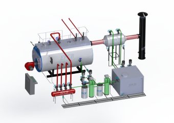
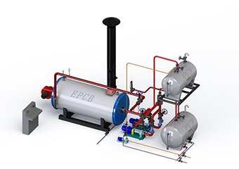
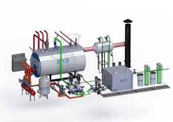
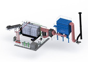





 Steam Boiler
 Thermal Oil Boiler
 Hot Water Boiler
 Steam Boiler
 Thermal Oil Boiler
 Hot Water Boiler
 Steam Boiler
 Thermal Oil Boiler
 Hot Water Boiler
 Steam Boiler
 Hot Water Boiler