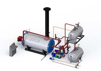
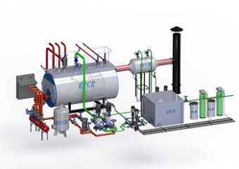
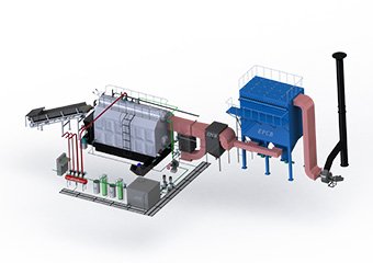
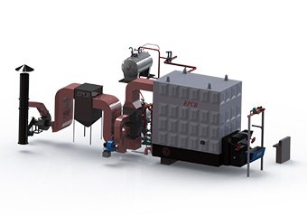
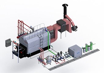
During the operation of the boiler, due to the failure or damage of auxiliary equipment, such as combustion equipment, water supply equipment, water treatment equipment, ventilation equipment, and dust removal and slag removal equipment, the boiler is forced to stop operation, which is called boiler failure.
Boiler failures often occur during the boiler operation. In the previous article, EPCB prepared a series of boiler safety content for everyone, analyzed common boiler accidents and failure causes, and gave corresponding preventive measures. Today, I will mainly introduce the boiler auxiliary equipment common malfunctions and solutions in boiler operation.
The boiler auxiliary equipment often fails: oil-fired gas boiler burners, water pumps, fans, water supply treatment equipment, etc. Through years of theoretical accumulation and field practice, EPCB has summarized these boiler auxiliary equipment common malfunctions and solutions.
Oil /Gas Boiler Burners

Burners Common Malfunction and Solution
1.The burner does not start
Phenomenon | Cause | Solution |
Burner does not start | no electricity | close all switches, check the fuse |
Limit or safety control device open | adjust or replace |
Control box lock | Press the control box reset button |
Motor lock | Press the thermal relay reset button |
The pump is broken | replace |
The fuse of the controller is disconnected | Replace |
Electrical connection error | Check electrical connection |
The control box is damaged. | Replace |
Motor control device is damaged | Replace |
Motor damaged | replace |
The capacitor is damaged | Replace |
The phototube is short-circuited | Replace |
Light leakage or simulated flame appears | Clear the light leakage or replace the controller |
2. The burner stops immediately after starting
Cause: lack of phase
Solution: Press the thermal relay reset button
3. The burner is locked immediately after pre-blowing, and the flame appears
phenomenon | Cause | Solution |
The burner is locked immediately after pre-blowing, and the flame appears | There is no oil in the fuel tank, or there is water at the bottom of the fuel tank | Refuel or drain |
The position of the combustion head or the air door is not suitable | For adjustment |
The solenoid valve cannot be opened | Check the wiring, and then change the coil |
The nozzle is clogged, dirty or damaged. | Eliminate or replace |
Ignition electrode position is wrong | Adjust and remove |
The grounding wire is not well insulated. | Replace |
The high-voltage cable is damaged. | Replace |
The ignition transformer is damaged. | Replace |
Incorrect wiring of solenoid valve or ignition transformer | Check |
The control box is damaged | Replace |
The pump does not start | start according to the operating rules |
The universal coupling between the pump and the motor is damaged | Replace |
Incorrect connection of inlet and return pipes | Correct |
The filter of the pump, filter or nozzle is dirty | Clean |
Wrong direction of motor | commutation |
4. The burner locks after the flame appears
phenomenon | Cause | Solution |
The burner locks up after the flame appears | The position of the ignition electrode is not correct | Adjust |
The photoelectric tube or the controller is damaged. | Replace |
Dirty photocell | clean |
5. Pulsating ignition or unstable flame
phenomenon | Cause | Solution |
Pulsating ignition or unstable flame | The position of the combustion head is set incorrectly | Adjust |
The position of the ignition electrode is wrong | Adjust |
Throttle is too big | adjust |
The nozzle is not suitable for this burner or boiler | Check and adjust |
The nozzle is broken | Replace |
Inappropriate pump pressure | Adjust according to the manual |
6. The burner can't burn a big fire
phenomenon | Cause | Solution |
The burner cannot burn a big fire. | The control system TR is not closed. | Adjust or replace |
The controller is damaged | Replace |
The second stage solenoid valve is damaged | Replace |
Hydraulic cylinder is damaged | Replace |
7. The second nozzle sprays oil but cannot reach the position of the damper
phenomenon | Cause | Solution |
The second nozzle sprays fuel but cannot reach the position of the damper. | The pump pressure is low | Increase |
Hydraulic cylinder is damaged | Replace |
8. Unstable oil supply
Cause: It may be caused by the pump or oil system
Solution: Keep the fuel tank close to the burner
9. Rust in the oil pump
Cause: There is water in the fuel tank
solution: drain the water in the fuel tank
10. There is noise and the oil pressure is unstable
Cause: there is air in the oil inlet pipe
solution: tighten the joint
11. The negative pressure value is too high (above 46.6kPa)
phenomenon | Cause | Solution |
The negative pressure value is too high (above 46.6kPa) | The height difference between the fuel tank and the burner is too large | Connect the burner with the annular oil circuit |
Pipe diameter is too small | increase |
Filter clogged | clean |
Inlet valve closed | open |
Wax precipitation at too low temperature | Add additives to light oil |
12. The pump does not start after a long interruption
phenomenon | Cause | Solution |
The pump does not start after a long interruption | The return pipe is not immersed in the oil | Return it to the height of the inlet pipe |
Air intake in the oil inlet pipe | Tighten the joint |
13. Pump leakage
Cause: oil leaking from sealing parts
Solution: change the pump
14. Smoke: black smoke
phenomenon | Cause | Solution |
Smoke: black smoke | insufficient air | adjust the combustion damper according to the manual |
Worn or dirty nozzle | Replace |
The nozzle filter is clogged, | clean and replace |
The pump pressure is wrong | adjusted to 1.0-1.4MPa |
Dirty fan | cleaning |
Dirty, loose or deformed flame stabilizing blades | Clean, tighten or replace |
15. Smoke: white smoke
phenomenon | Cause | Solution |
Smoke: white smoke | furnace resistance is too large | expand |
Too much air | Adjust the damper according to the manual |
16. Dirty burning head
phenomenon | Cause | Solution |
Dirty combustion head | Dirty nozzle or filter | Replace |
Nozzle oil volume or angle is not suitable. | Refer to recommended nozzles |
Nozzle loose | tighten |
There are debris on the fire stabilizing blades | Clean |
The combustion head is calibrated incorrectly or the air is insufficient. | Adjust and open the valve according to the instructions |
The length of the induced draft pipe is not suitable for the boiler. | Refer to the boiler section |
17. The burner does not start
phenomenon | Cause | Solution |
Burner does not start | Limit control device is open | Adjust or replace |
Control box lock | reset |
No gas supply | Open the manual valve close switch between the flow meter or the valve group or check the connection |
No power supply | Check the connection |
Control box fuse blown | Replace |
The contact point of the servo motor is not calibrated | Adjust the cam or replace the servo motor |
Insufficient gas supply pressure in the main line. | Contact the gas company |
The minimum gas pressure switch is not closed | Adjust or replace |
The air pressure switch is in the running position. | Replace |
The control box is damaged. | Replace |
Motor damaged | replace |
18. The burner does not start but locks up
Cause: there is a simulated flame
Solution: replace the control box
19. The burner starts but stops at the maximum damper position
Cause: The contact of the servo motor of cam 2 did not reach the terminal of the operation control panel
Solution: adjust cam 1 or replace the motor
20. The burner starts but immediately stops
Cause: no midline
Solution: lay out the neutral line when three-pole power supply
21. The burner is locked after starting
phenomenon | Cause | Solution |
The burner is locked after starting | The air pressure switch is not adjusted. | Adjust or replace. |
The pressure measuring tube of the pressure switch is clogged | Clean |
Dirty fan | cleaning |
The head is not adjusted properly | adjust |
Burner back pressure is too high | Find pressure difference |
Flame detection circuit failure | Replace control box |
22. The burner stays in the pre-purge stage
Cause: the servo motor contact of cam 3 does not function as the control box terminal
Solution: adjust cam 3 or replace the servo motor
23. After the pre-purge and safety time, the burner is locked and the flame does not appear
phenomenon | Cause | Solution |
|
After the pre-purge and safety time, the burner is locked and the flame does not appear. | The solenoid valve can only let a small amount of gas pass through. | Increase the outlet pressure of the regulator |
Gas pressure is too low | adjust |
The ignition electrode is not adjusted correctly. | Adjust |
There is air in the pipe | Purge air |
Incorrect electrical connection of valve or ignition transformer | Reconnect |
The ignition transformer is damaged. | Replace |
High pressure device is damaged | Replace |
The solenoid valve cannot be opened. | Replace the coil or correct the panel |
24. The burner locks when a fire occurs
phenomenon | Cause | Solution |
|
The burner locks when a fire occurs | There is a problem with the ion probe connection. | Reconnect |
Insufficient ion current (less than 6μA | check probe position |
Connect the probe, | remove or replace the cable |
Maximum gas pressure switch function | Adjust or replace |
25.Burner repeated start section without locking
Cause: The main line gas pressure is very close to the value set by the minimum gas pressure switch. After the solenoid valve is opened, the change of air pressure causes the pressure switch to open itself, the solenoid valve is immediately closed, the burner stops, the pressure starts to rise again, the gas pressure switch is closed again, and the ignition cycle is repeated, and this is repeated.
Solution: reduce the operating pressure of the minimum gas pressure switch or replace the gas filter
26. Locked but no symbol indication
Cause: simulated flame
Solution: Replace the controller
27. Burner locks up during operation
phenomenon | Cause | Solution |
|
Burner locks up during operation | Probe or ion cable is grounded | Replace broken parts |
Air pressure switch failure | Replace |
Maximum gas pressure switch function | Adjust or replace |
28. Lock when the burner is shut down
Cause: there is still flame or simulated flame in the combustion head
Solution: clear the flame or replace the control box
Burner maintenance
1. Burner Cleaning and maintenance
Loosen the burner hinge shaft and open the burner head, clean the burner parts with detergent or a rag, check and adjust the ignition rod gap, wipe the flame detector with a clean soft cloth, and carefully clean the air duct and fan impeller.
2. Maintenance of the oil circuit system
Disassemble the fuel line, clean the filter, and open the drain valve of the daily fuel tank to remove water and oil impurities.
3. Maintenance of the circuit system
Check whether the connection points are firm and the contact components are intact.
Water Pump

1.Reciprocating pumps
Reciprocating pumps Common malfunction and solutions
Common failures | Causes | solutions |
The water pump cannot start after opening the steam valve | 1. The sliding valve is just in the middle position, the steam inlet and exhaust port are blocked, and steam cannot enter the cylinder 2. The steam pressure is too low 3. The valve on the water supply pipe or exhaust pipe is not open 4. The seal of the valve stem is too tight, or the mechanical part is stuck. | Repair or improve according to the specific situation |
The water pump does not output water after starting | 1. The valve on the water supply pipe or the exhaust pipe is not opened 2. The piston ring of the water tank or air cylinder is damaged 3. The pressure pad or packing is not tight, and air has leaked into it 4. The feed water temperature is too high and vaporization occurs. 5. The water tank lacks water. | Repair or improve according to the specific situation. |
There is a crashing sound when the water pump is running | 1. The moving speed of the piston is too fast 2. The pin connecting the nut on the piston or piston connecting rod falls off 3. The valve is damaged, or the pump is improperly assembled |
The temperature of the transmission parts rises sharply | 1. The packing gland is too tight 2. The lubricating oil is insufficient, or the oil circuit is blocked |
The pump suddenly stops running | 1. The valve on the water supply pipe is blocked or closed 2. The connecting piece on the piston rod is damaged, or the cross joint is stuck in the guide groove |
2. Electric centrifugal pump
Electric centrifugal pumps Common malfunctions and solutions
Common failures | Causes | solutions |
No water is discharged after the pump is started | 1. The suction valve is immersed in the water and not drained, or blocked by debris 2. The water diversion is not full, the air in the pump is not drained, or the air leaks at the suction pipe joint 3. The impeller reverses, or the speed is too low 4. The head is too high or the resistance of the pipeline is too high, which exceeds the working capacity of the pump. | Repair or improve according to the specific situation. |
During operation, the preload or head decreases | 1. The working pressure of the boiler increases 2. The impeller speed is reduced due to voltage drop and other reasons 3. Poor sealing performance of the suction pipe, resulting in air leakage 4. The water level of the water source drops and the water absorption height increases 5. The suction valve is partially blocked. | Repair or improve according to the specific situation |
Bearing temperature rises sharply | 1. The quality of lubricating oil is not good, or the amount of oil is insufficient 2. The shaft is bent, or the bearing ball is damaged 3. Improper bearing and bearing clearance, or the concentricity of the water pump shaft and the motor shaft does not meet the requirements |
Vibration and noise | 1. The impeller is partially blocked and rubs against the shell 2. The shaft is bent, or the bearing is worn 3. The center line of the water pump shaft and the motor shaft are misaligned 4. The fixing device of the suction pipe or the outlet pipe is loose 5. The resistance in the suction pipe increases, or the water output is too large 6. Loose anchor bolts |
The pointer of the pressure gauge jumps violently | 1. The joint of the pressure gauge is leaking 2. Vibration occurs in the pump body or pipeline 3. The hole of the cock is too large and the water impulse is too strong |
The pump consumes too much power | 1. The packing is too tight, or the impeller and the shell are rubbed, causing the rotating part to heat up and expand, and the resistance increases 2. The water output or head exceeds the design value, and the pump is running at overload |
Fans

Fans Common malfunction and solutions
Common failures | Causes | solutions |
Bearing box vibration | 1. The center line of the fan shaft and the motor shaft is staggered, or the coupling is skewed 2. The impeller is deformed, or the rivets on the impeller are loose 3. The foundation is unstable, or the anchor bolts are loose 4. Rotor imbalance causes friction 5. The seal is too tight and causes friction | repair or improve according to the specific situation |
Bearing temperature rises sharply | 1 The lubricating oil is of poor quality or polluted and deteriorated, and the amount of oil is insufficient 2. The cooling water pipe is blocked 3. Improper installation of the bearing, or sliding of the inner and outer steel rings 4 The bearing is seriously worn 5Bearing gland bolts are too tight | repair or improve according to the specific situation |
Insufficient air volume and air pressure | 1 The speed does not reach the rated value 2 The air inlet or outlet is partially blocked 3 The blade falls off, deforms or is severely worn 4. The shell is worn and has serious air leakage |
Water Supply Treatment Equipment

Water Supply Treatment Equipment Common Malfunctions and solution.
At present, the sodium ion exchanger widely used in boiler feed water treatment equipment.
Common failures | Causes | solutions |
The flow rate of the ion exchanger is not enough | 1. The replacement layer is too high 2. The head resistance of the water inlet pipe or the drainage system is too large (suspended matter pollution, resin particles broken) | 1. Appropriately reduce the height of the resin 2. Change the inlet pipe or drainage system to strengthen recoil |
There is a loss of normal resin particles during the reverse selection process | 1. The drain cap is broken 2. Excessive backwash strength 3. Uneven flow velocity distribution on the cross section of the exchanger 4. There are bubbles in the resin | 1. Replace the drain cap 2. Reduce backwash strength 3. Overhaul the water inlet system 4. Drain the bubbles |
The amount of water produced in cycles is reduced. | 1 The amount of salt used for regeneration is too small. 2 The concentration of the salt solution is too low 3 Too much salt impurities for regeneration 4 The flow rate of the salt solution is too fast during regeneration, and the contact time with the resin is not enough 5 Resin is contaminated by suspended matter 6 There are more cations such as Fe and Al in the inlet water, and the resin is poisoned. 7Insufficient backwashing strength, incomplete backwashing 8 The washing time is too long and the amount of water is too large 9 The drainage system is damaged and the water flow is uneven 10. The hardness of the water source increases | 1. Increase the amount of salt used for regeneration 2. Increase the concentration of the salt solution 3. Use chemical analysis methods to determine the quality of NaCl, and if necessary, use Na2CO3 to soften the salt solution 4. Slow down the flow rate of the regeneration salt solution 5. The inlet water is filtered to clarify, increase the backwash intensity, and thoroughly clean the resin particles 6. Clean with 5% HCL resin or acidified salt with pH=3-5; raw water pretreatment to reduce Fe and Al content; the inner wall of the exchanger is protected by an anticorrosive coating 7. Adjust the backwash water flow and pressure 8. Reduce the washing time 9. Stop tank overhaul 10. Pay attention to water quality changes or replace water sources |
The amount of salt used for regeneration is too large | 1 The flow rate of the salt solution is too fast 2Uneven distribution of salt solution 3. Too many impurities in the salt solution 4. The concentration of the salt solution is too high | 1. Adjust the flow rate of the salt solution 2. Overhaul the salt solution system 3. Strengthen the clarification and filtration of salt solution 4. Adjust the salt concentration |
During the whole operation process, the hardness of soft water is always not up to the requirement | 1. The sodium salt concentration of edema is too large (generally the salt content is more than 1000mg/L) 2. The surface of the resin particles is contaminated 3. The brine valve is not tight 4. In the parallel system, the outlet valve of the regenerating exchanger is open or not tight 5. The exchanger layer is not high enough or the running flow rate is too high 6. The water temperature is too low (<10℃) | 1. Change to secondary sodium softening system 2. Reduce the impurities in raw water and brine, and strengthen backwashing 3. Repair and replace the brine valve or install two valves 4. Close or repair and replace the water outlet valve 5. Properly increase the height of the exchanger layer or reduce the operating speed 6. Properly increase the inlet water temperature |
Increased chloride ion content in soft water | 1. Incorrect operation, open the operating brine valve during regeneration, or the valve is not tight, or open the regeneration tank outlet valve 2. The salt solution valve is lax or the water outlet valve is lax | 1. Strictly implement the operating procedures and correct the error operate 2. Repair and replace the valve in time, but whether it is an operation problem or equipment defect, you should pay attention to the supervision of the chlorine in the pot water and strengthen the sewage discharge. |
Conclusion:
Through the above content, you can have a comprehensive understanding of the common faults of boiler auxiliary equipment, understand the boiler faults and take corresponding measures to actively prevent them, and your boiler can be used more safely and lastingly.
EPCB, your private boiler system expert!
Further Reading:
Boiler Safety Series | Boiler Tube Burst Causes and Preventive Measures in Boiler Accidents
Boiler Safety Guide | Industrial Boilers'Common Accidents and Solutions
Boiler Safety Series | Boiler Water Level Accidents Causes and Preventive Measures
Boiler Safety Series| Common Malfunctions and Solutions inside the Boiler
Boiler Safety Accessories and Valves Common Malfunctions and Solutions
Boiler Safety Series|Boiler Explosion Accident Phenomenon and Preventive Measures


 Steam Boiler
 Thermal Oil Boiler
 Hot Water Boiler
 Steam Boiler
 Thermal Oil Boiler
 Hot Water Boiler
 Steam Boiler
 Thermal Oil Boiler
 Hot Water Boiler
 Steam Boiler
 Hot Water Boiler